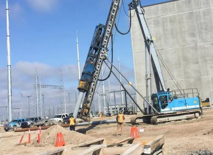

Piles are used for resisting vertical and lateral loads that are transmitted to the substructure of buildings. Structures such as tall chimneys, highrise buildings, towers, offshore structures, tall retaining structures, wharfs and jetties, etc are normally subjected to high lateral loads, which are subsequently transferred to the foundations supporting them as lateral shears. If the lateral loads are too high, inclined or batter piles can be used to aid vertical piles for lateral load resistance ( Murthy, 2012 ). The analysis of laterally loaded piles to determine the ground deflection, bending moment, shears, load-carrying capacity, etc is therefore very important for the purpose of design.

Figure 1: Inclined concrete piles in a marine facility
Numerous researchers have worked on the experimental and theoretical solution to the problem of laterally loaded piles. Reese et al (1974) and Matlock (1970) developed the concept of p-y curves for solving laterally loaded pile problems. The method is quite popular in the United States of America. However, the p-y curve method has been reported to not predict pile response properly ( Kim et al. 2004 , Anderson et al. 2003 ).
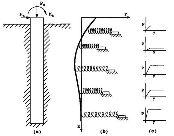
Figure 2: Model of laterally loaded pile: (a) elevation view; (b) as elastic line; (c) p-y curves,
According to Basu et al (2008) , the failure of p-y curves to predict pile response properly is not surprising because the p-y curves, which describe the resistive properties of soil as a function of pile deflection, used in the p-y analysis are developed empirically by back-fitting the results of numerical analysis to match the actual field pile-load test results. Thus, p-y curves developed for a particular site are not applicable to other sites. In order to obtain an accurate prediction of lateral pile response by the p-y method, p-y curves must be developed through pile load tests for every site – an uneconomical alternative.
The problem of laterally loaded piles is closely related to the problem of beam on elastic foundation. While a beam on an elastic foundation can be loaded at any point along its length, the external loads on a pile are likely to be on or above the ground surface.
Most of the numerical solutions for laterally loaded piles involves the concept of modulus of subgrade reaction. This is based on Winkler’s assumption that a soil medium may be approximated by a series of closely spaced independent elastic springs ( Murthy, 2012 ). It has been shown that the error inherent in Winkler’s hypothesis is not significant. Therefore in laterally loaded piles, a series of non-linear springs can be used to represent the force-deformation characteristics of the soil.
The key to the solution of laterally loaded piles problem, therefore, lies in the determination of the modulus of subgrade reaction with respect to depth along the pile. The soil reaction p at any point along the pile length x may be expressed as;
where y is the deflection at point x, and Es is the soil modulus.
The relationship between the soil resistance per unit length (p) and deflection (y) is strongly non-linear. Therefore, Es is not constant but changes with the deflection of the pile. There are many factors that influence the value of Es such as the pile width, the flexural stiffness, the magnitude of the applied load, and the soil properties.
The variation of Es with depth for any prticular load level may be expressed as;
Where nh is the coefficient of soil modulus variation. The variation of nh with relative density Dr of sand is given in the Figure below;
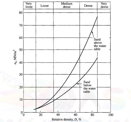
Figure 3: Variation of nh with relative density Dr
Matlock and Reese (1960) provided a non-dimensional solution for the determination of deflection, slope, moment, shear, and soil reaction any point x along the pile. The equations are as follows;
Where T is the relative stiffness factor expressed as;
A and B are sets of non-dimensional coefficients that can be picked from Table ( see Table 16.2, Murthy, 2012 ). The coefficients are given as functions of the depth coefficient Z expressed as;
For free headed piles at the ground level, the deflection and slope are as given below;
For fixed head piles;
The bending moment at ground level for fixed head is;
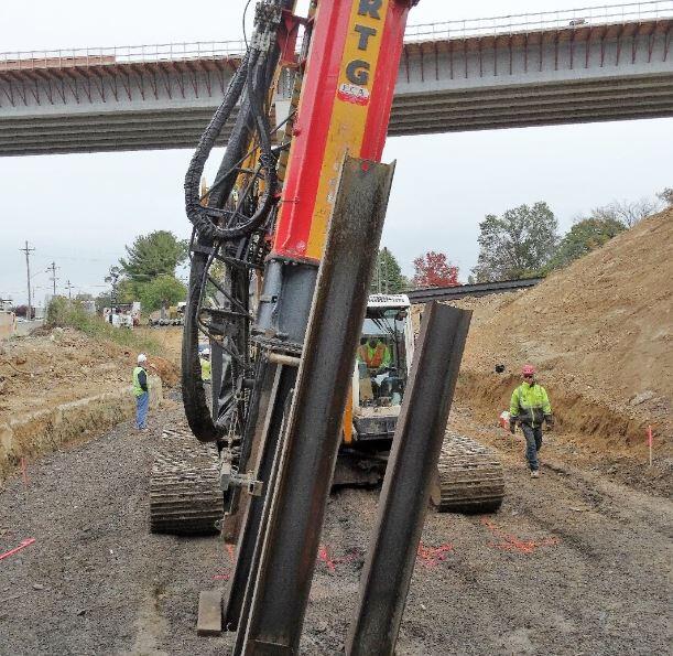
Figure 4: Driving of inclined H-steel piles
Broms’ (1964a, 1964b) developed solutions for determining lateral deflections at ground level at working loads and ultimate lateral resistance of piles under lateral load using the concept of subgrade reaction. He developed solutions for long and short piles installed in cohesive and cohesionless soils in the form of charts.
Furthermore, laterally loaded piles are usually analysed depending on whether the head is free to rotate or fixed. The head of a pile may be considered as fixed when the stiff pile cap is tied using connecting beams.
Ultimate Lateral Resistance of Piles In Saturated Clays
The ultimate soil resistance of piles in cohesive soils increases with depth from 2cu (cu is the undrained shear strength) to 8 to 12cu at a depth of 3 times the pile diameter (3d) from the ground surface. However, Broms suggested a constant value of 9cu to be used as the ultimate soil resistance below a depth of 1.5d.
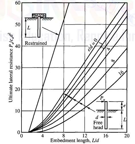
Figure 5: Ultimate lateral load of short pile in cohesive soil (
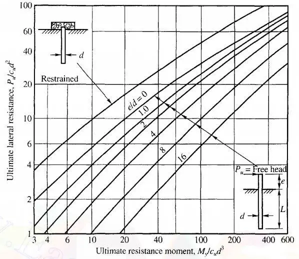
Figure 6: Ultimate lateral load of long pile in cohesive soil (
The solution for long piles involves the moment capacity of the pile section which should be calculated accordingly. A free-headed pile is considered long when βL > 2.5 and short when βL < 2.5. For a fixed-headed pile, a pile is long when βL > 1.5 and short when βL < 1.5.
Where;
EI = stiffness of the pile
k = coefficient of horizontal subgrade reaction
d = width or diameter of pile
L = Length of pile
Ultimate Lateral Resistance of Piles in Cohesionless Soil
The ultimate lateral resistance of long and short piles embedded in cohesionless soils can be estimated from the chart below. For short piles, the dimensionless quantity Pu/γd 3 Kp is plotted against the L/d ratio while in long piles, Pu/γd 3 Kp is plotted against My/γd 4 Kp.
Where;
γ = the effective unit weight of the soil
Kp =Rankine’s passive earth pressure coefficient
My = Ulitimate moment capacity of the section
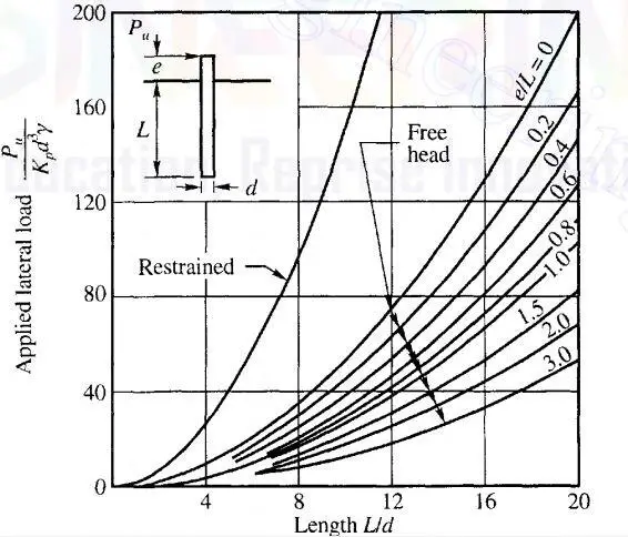
Figure 7: Ultimate lateral load of short pile in cohesionless soil (
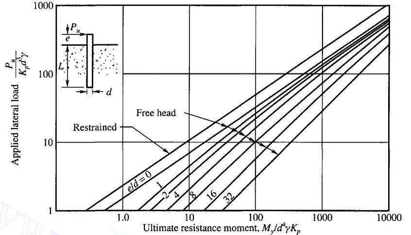
Figure 8: Ultimate lateral load of long pile in cohesionless soil (
Solved Example
A reinforced concrete square pile of dimensions 450 x 450 mm is driven to a depth of 20m in medium dense sand. The sand is in a saturated state. A lateral load of 250 kN is applied to the pile at 1 m at the ground level. Calculate the following;
(a) Lateral deflection of the pile at the ground level when the head is free (Use Matock and Reese Method)
(b) Lateral deflection of the pile at the ground level when the head is restrained (Use Matock and Reese Method)
(c) Ultimate lateral resistance of the pile (Using Brom’s method)
(nh = 15000 kN/m 2 /m; fcu = 40 N/mm 2 ; Asprov = 12Y20 (3768 mm 2 ); φ = 35 o ; Mu = 445 kNm; Submerged unit weight of soil = 8.75 kN/m 3 )
Solution
Ignoring the reinforcements, the flexural rigidity of the pile can be calculated;
fcu = 40 N/mm 2
Ec = 20 + 0.2fcu = 20 + 0.2(40) = 28 kN/mm 2 = 2.8 × 10 7 kN/m 2
I = bh 3 /12 = (0.45 × 0.45 3 )/12 = 3.417 × 10 -3 m 4
Hence;
EcI = (2.8 × 10 7 ) × (3.417 × 10 -3 ) = 95676 kNm 2
T = (EI/nh) 0.2 = (95676/15000) 0.2 = 1.448 m
(a) Lateral deflection at the ground when the head is free
Using Matlock and Reese method
yg = 2.43(PtT 3 )/EI + 1.62(MtT 3 /EI)
Pt = 250 kN (given)
Mt = (250 × 1m) = 250 kNm
yg = 2.43(250 × 1.448 3 )/95676 + 1.62(250 × 1.448 2 )/95676 = 0.0192 + 0.008875 = 0.028 m = 28 mm
Extra
Using Brom’s method;
η = (nh/EI) 0.2 = (15000/95676) 0.2 = 0.69
ηL = 0.69 × 20 = 13.8
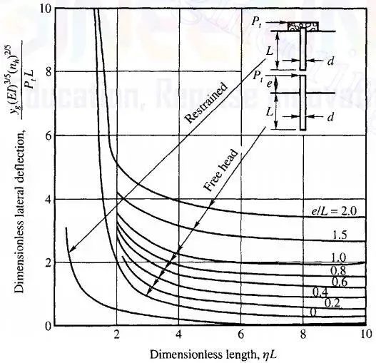
Figure 9: Chart for deflection of laterally loaded piles in coheiosnless soild (
Therefore yg = 0.2PtL/(EI) 3/5 (nh) 2/5 = (0.2 × 250 × 20)/(95676 3/5 × 15000 2/5 ) = 0.0219 mm = 21.9 mm
When analysed on Staad Pro, a lateral deflection of 24.07 mm was obtained as shown in Figure 10;
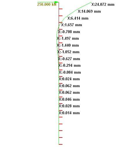
Figure 10: Staad Pro numerical modelling results
(b) Lateral deflection when the head is restrained
Using Matlock and Reece method
yg = 0.93(PtT 3 )/EI = 0.93(250 × 1.448 3 )/95676 = 0.007377 = 7.38 mm
Extra
Using Brom’s method;
[yg(EI) 3/5 (nh) 2/5 ]/PtL = 0 (when the head is restrained)
Hence the lateral deflection can be taken as zero.
(c) Lateral load resistance of the pile
Coefficient of pasive pressure Kp = (1 + sinφ)/(1 – sinφ) = (1 + sin35)/(1 – sin35) = 3.69
Ultimate moment of resistance of section = 445 kNm
γ = 8.75 kN/m 3
d = 0.45 m
Hence, the non-dimensional yield moment = M/γd 4 Kp = 445/(8.75 × 0.45 4 × 3.69) = 336
For e/d = 1000/450 = 2.22
Reading from chart;
Pu/γd 3 Kp = 60 (for free-head condition)
Pu/γd 3 Kp = 80 (for fixed head condition)
Therefore,
Pu,free = 70γd 3 Kp = 60 × 8.75 × 0.45 3 × 3.69 = 176.5 kN
Pu,fixed = 70γd 3 Kp = 80 × 8.75 × 0.45 3 × 3.69 = 235 kN
Therefore, the pile section provided is inadequate for the service lateral load coming to the substructure. The pile section will have to be changed.
References
Anderson, J. B., Townsend, F. C. & Grajales, B. (2003): Case history evaluation of laterally loaded piles. J. Geotech. Geoenv. Engng., Am. Soc. Civ. Engrs. 129, No. 3, 187-196.
Basu D., Salgado R., Prezzi M. (2008): Analysis of Laterally Loaded Piles in Multilayered Soil Deposits. Publication FHWA/IN/JTRP-2007/23. Joint Transportation Research Program, Indiana Department of Transportation and Purdue University, West Lafayette, Indiana, 2008. doi: 10.5703/1288284313454
Broms B.B. (1964a): Lateral Resistance of Piles in Cohesive Soils. Journal of the Soil Mechanics and Foundations Division, 1964, Vol. 90, Issue 2, 27-6
Broms B.B. (1964b): Lateral Resistance of Piles in Cohesionless Soils. Journal of the Soil Mechanics and Foundations Division, 1964, Vol. 90, Issue 3, 123-156
Kim, T. K., Kim, N-K, Lee, W. J. & Kim, Y. S. (2004). Experimental load-transfer curves of laterally loaded piles in Nak-Dong river sand. J. Geotech. Geoenv. Engng., Am. Soc. Civ. Engrs. 130, No. 4, 416-425.
Matlock H. (1970): Correlations for Design of Laterally Loaded Piles in Soft Clay. Proceedings to the 2nd Offshore Technology Conference, Houston Texas, Vol 1
Murthy V.N.S. (2012): Soil Mechanics and Foundation Engineering. CBS Publishers and Distributors Pvt. Ltd, New Delhi, India
Reese, L.C. (1997): Analysis of laterally loaded piles in weak rock. J. Geotech. Geoenviron. Eng. 123 (11), 1010–1017
Reese, L.C., Cox, W.R., Koop, F.D.: Field testing and analysis of laterally loaded piles in stiff clay (1974): In Proceedings of the 6th Annual Offshore Technology Conference, pp. 672–690. Houston, Texas, 2(OTC 2312)